Conductors, overcurrent protection, and grounding/bonding

Chapter 2 — Wiring and Protection

Master conductors, overcurrent protection, grounding/bonding, and enclosure rules—the backbone of safe installs.

10
Major Articles
15
Quiz Questions
20
Visual Examples
🧠

240 — Overcurrent Protection Basics

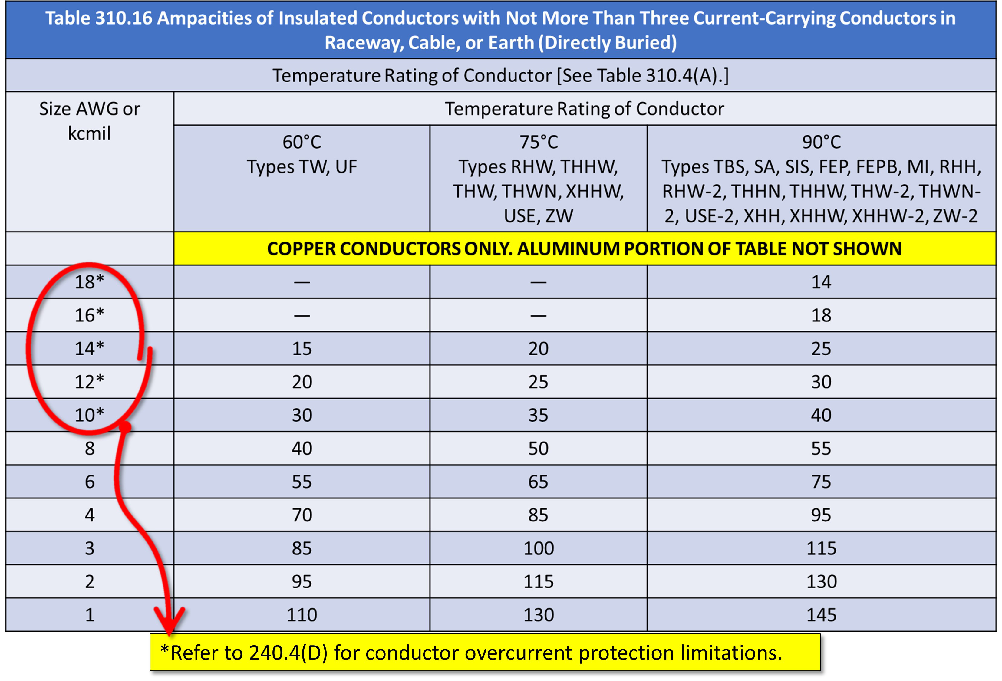
  • 240.4Conductors must be protected per their ampacity. Small conductor rules are not blanket allowances—only certain sizes (14, 12, 10 AWG) can round up when allowed.
  • 240.21Tap conductors: 10-ft, 25-ft, and feeder tap rules all differ. Each has conditions (length, termination, protection) that must all be met. Examiners love to mix them.
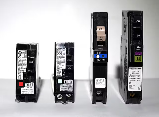
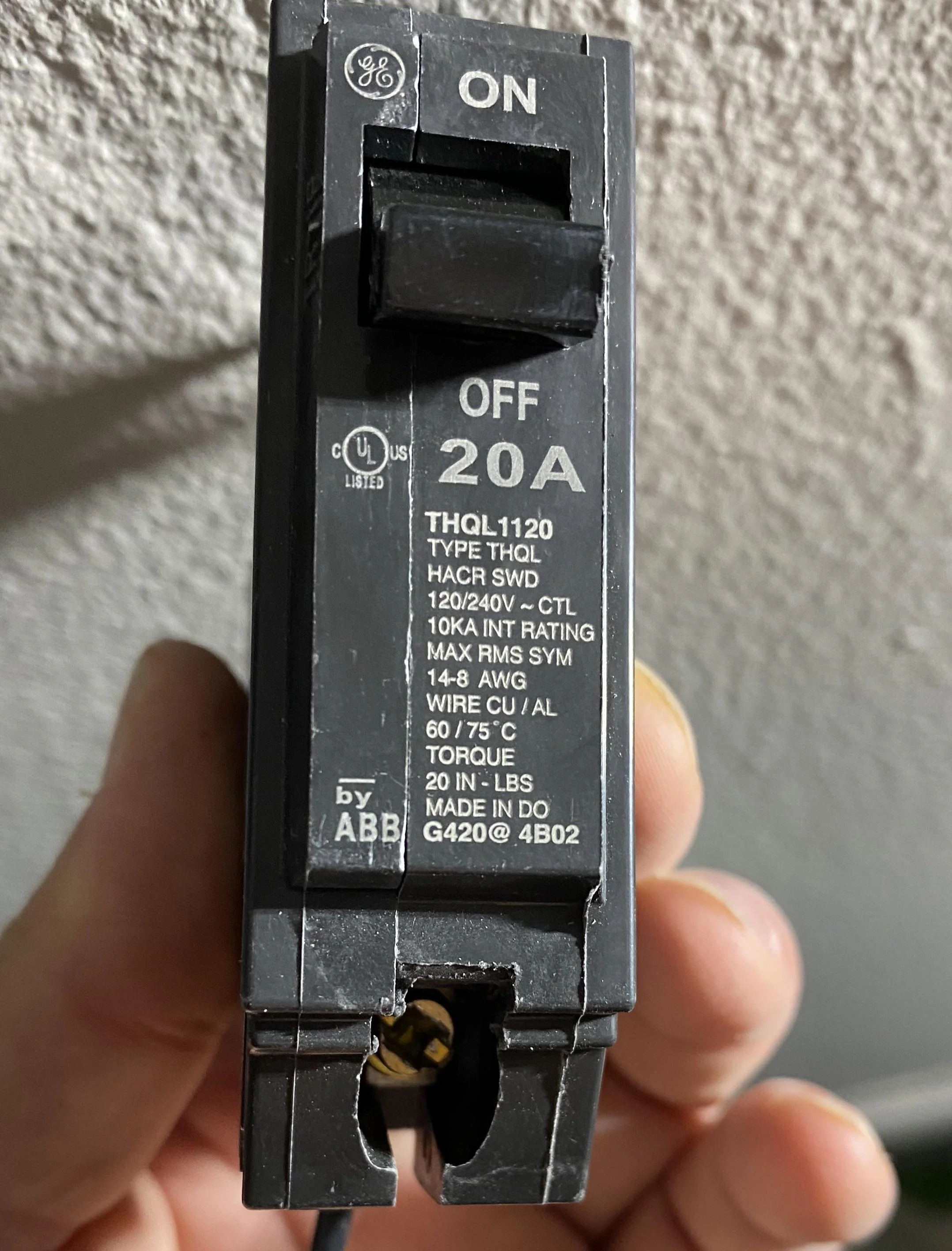
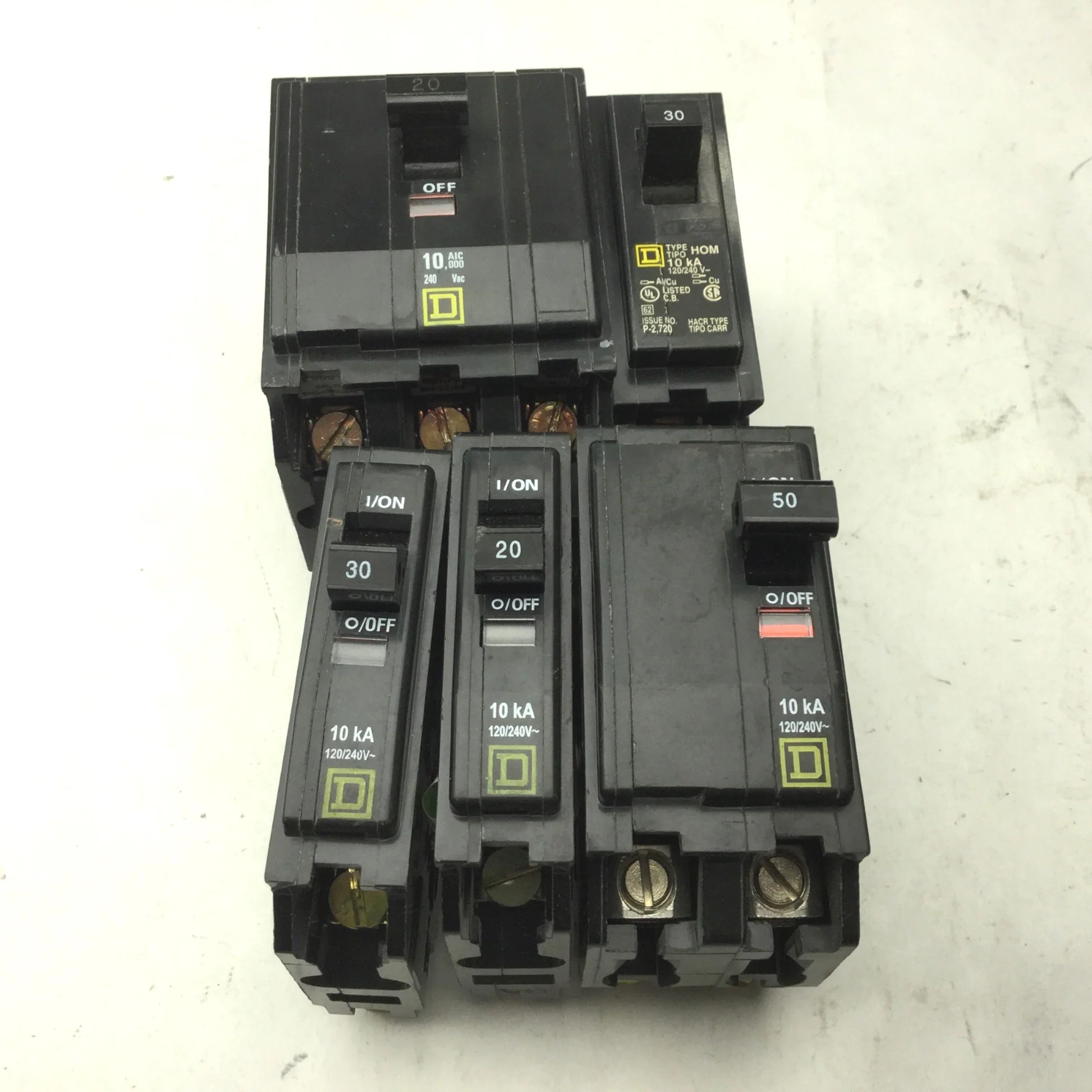
  • 240.6Standard breaker sizes: 15, 20, 25, 30, 35, 40... If you see 45A or 55A, that's not standard—use next standard size rules only when another Code article permits.
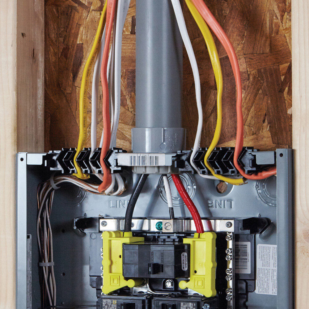
  • 240.10Protective devices can't be used as switches unless they're identified for that function. That includes many breakers—but check the marking.
EXAM TRAP
NEXT SIZE UP
240.4(B) doesn’t apply to every circuit. It’s limited to specific small conductor cases. If a question asks about rounding up on #2 AWG, the answer is no.
Assorted breakers
Memorize standard ratings and the exceptions for rounding up.
Tap diagram
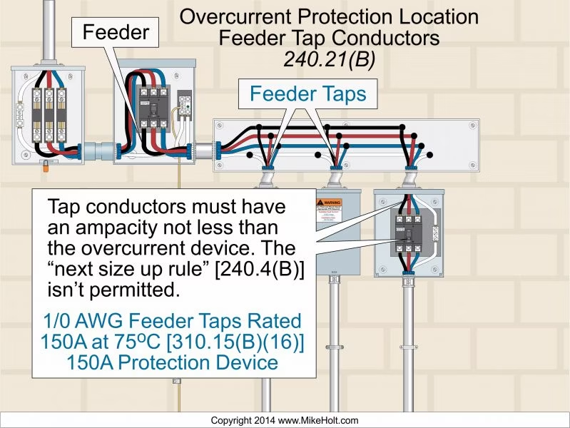
Tap rules = strict length and protection requirements.
🔌

310 — Conductor Ampacity (310.16)

  • TerminationsUse the lowest rated termination in the circuit. Example: a #8 copper in a 90°C column still gets limited to 75°C if the breaker is only rated 75°C.
  • Adjustment FactorsAmbient temp and bundling derate values. Example: 10 current-carrying conductors in a raceway = 50% derating. Always apply before checking OCPD.
  • Material DifferencesAluminum and copper-clad aluminum run larger for the same ampacity. Never assume equivalence by size alone—always verify with the table.
  • 90°C Column UseYou can sometimes use 90°C values for adjustment only, then step back to 75°C for termination. This nuance shows up on exams.
TABLE
QUICK SHEET — 75°C COPPER (COMMON)
Conductor (Cu)75°C Ampacity (A)
#1225
#1035
#850
#665
#485
#3100
#2115
Examples before any derating. Always confirm in 310.16 and apply ambient/bundling factors.
Ampacity table highlight
310.16: memorize the key conductor sizes.
Conductor bundle
Bundling causes derating—watch for >3 current-carrying conductors.
🧲

250 — Grounding & Bonding (Core Concepts)

  • 250.4(A)Grounding connects the system to earth. It stabilizes voltage during lightning or surges but doesn't clear faults.
  • 250.4(B)Bonding connects metal parts together to create a low-impedance fault current path so breakers trip fast.
  • Fault PathBond enclosures, raceways, and equipment grounds. A loose connection in the path = breaker won't trip.
  • Service vs SDSService equipment requires a main bonding jumper; separately derived systems (like transformers) require a system bonding jumper.
NEC REFERENCE
250.4
Bonding provides the effective fault-current path. Grounding stabilizes voltage. Exams love to flip the terms.
Bonded equipment
All metal enclosures must be bonded together.
Service bonding jumper
Know your MBJ vs SBJ requirements.
🌍

250 — Grounding Electrode System

  • 250.50If an electrode is present, you must use it. Ufer (concrete-encased), building steel, and metal water pipe all count.
  • 250.52Ground rods are last-resort electrodes. If used, you often need two rods 6 ft apart unless one rod measures ≤25Ω.
  • 250.66GEC sizing is based on the largest ungrounded service conductor. Parallel conductors change the math—don't miss this detail.
  • 250.64GECs must be continuous or irreversibly spliced. Protect them from physical damage.
RULE OF THUMB
USE WHAT’S THERE
If concrete-encased rebar (Ufer) exists, you must use it. Ground rods aren’t first choice—they’re backup electrodes.
Ufer connection
Concrete-encased electrodes are stable and required if present.
Bonded rebar clamp
Only use listed clamps for connections.
📦

300 — Wiring Methods & Boxes

  • 300.4Protection from nails and screws: maintain burial depth or use plates where required.
  • 300.15All splices and terminations must be inside boxes or fittings. No 'free air' splices.
  • 300.20Ferrous raceways: keep all conductors of a circuit together to prevent induced heating.
  • 300.12Raceways must be continuous and secured. Broken or incomplete raceways = violation.
JOBSITE HORROR STORY
HIDDEN SPLICE
A free splice hidden behind drywall caused intermittent faults for years before a fire exposed it. All splices must be inside approved boxes with covers.
Nail plate
Plates protect where raceways or cables are too close to edges.
Box with cover
Covers are required for all junction and device boxes.
🔌

210 — Branch-Circuit Basics

  • 210.52Dwelling unit spacing: 6 ft/12 ft wall spacing, small appliance and laundry branch requirements.
  • 210.8GFCI protection required in bathrooms, kitchens, outdoors, basements, laundry areas, and more.
  • 210.12AFCI protection now applies broadly—most habitable dwelling spaces need it.
  • 210.19Conductors must be sized for continuous load at 125%. Voltage drop recommendations also apply (3% branch, 5% feeder+branch).
TABLE
KITCHEN/LAUNDRY QUICK MAP
Location / ItemRequirement
Kitchen/Dining Small-Appliance2 × 20A circuits (minimum)
Laundry1 × 20A dedicated
Countertops6 ft / 12 ft spacing rule applies
GFCIPer 210.8 locations (kitchen, bath, outdoors, etc.)
AFCIMost habitable rooms; see 210.12
Plan these on your one-line and layout before rough-in.
Kitchen outlets
Spacing rules and GFCI protection are strictly enforced.
AFCI/GFCI breakers
Many panels now use dual-function breakers.
🧯

225 — Outside Feeders & Branch Circuits

  • 225.31Each building requires its own disconnecting means for feeders/branch circuits.
  • 225.18Overhead conductor clearances: 10 ft over walking, 12 ft over residential driveways, 18 ft over public streets.
  • 225.32Disconnects must be readily accessible and located at the building served.
CHART
OVERHEAD CLEARANCES (QUICK SHEET)
AreaMinimum Clearance
Pedestrian walkway10 ft
Residential driveway12 ft
Public street18 ft
Heights vary with conditions and voltage—this hits the common exam set.
Outside disconnects
Grouped and labeled disconnects at building entry.
Overhead spans
Different areas require different minimum heights.
🧰

240/310 — Continuous Loads & Sizing

  • 125% RuleContinuous loads (≥3 hours) require OCPD ≥125% of load and conductor sized accordingly.
  • Termination TempSize conductors using the proper temperature rating of equipment terminals (usually 60°C or 75°C).
  • Listing ImpactManufacturer listings override default rules. If a panel label restricts breaker type or rating, follow it.
EXAM TRAP
125% MEANS WHAT?
Don’t confuse conductor ampacity sizing with OCPD rating. Questions often twist the 125% rule to trip you up.
Load calc sheet
Perform load calculations step by step.
Breaker with label
Follow listed limitations.
🔩

312/314 — Cabinets, Panels, & Boxes

  • 312.6Minimum wire-bending space inside panels must be maintained—dimensions vary by wire size.
  • 314.16Box fill calculations: count each conductor, device, and clamp properly. The math is enforceable.
  • 312.5Cables entering cabinets must be secured with fittings and bushings as required.
RULE OF THUMB
RULE — MATH WINS
Box fill and bending space are not guesses. They’re measured and calculated. Errors = failed inspection.
Panel gutter
Maintain bending space at terminals.
Box fill count
Count each item per 314.16 allowances.
🪵

240/225 — Disconnecting Means

  • 230.71Service disconnects historically limited to 6; newer cycles often limit to 2 service disconnects—verify local adoption.
  • 225.33Feeder disconnects must be grouped and clearly marked.
  • 225.32Outside building disconnect location: at the building served and readily accessible.
TABLE
DISCONNECT QUICK MAP
ItemRule of Thumb / Reference
Service disconnect(s)Legacy 6; newer cycles often 2 — check local 230.71 adoption
Feeder disconnect(s)Must be grouped and labeled (225.33)
Outside-building disconnectAt building served; readily accessible (225.32)
Sketch these on your one-line so the differences stick.
Grouped disconnects
Group disconnects together in one location.
Lockable handle
Use listed lock-open features where required.

Chapter 2 — Field Quick Hits

310.16 Discipline

Temp rating limits + ambient + bundling. Do it in order.

210 Spacing/Protection

Kitchen/laundry spacing & GFCI/AFCI—update each cycle.

Bond vs Ground

Bond metal together, ground systems—fault path wins.

125% Continuous

Know what gets 125% and why.

Box/Bend Math

Do the fill/bend math before rough-in.

Tap Rules

Length, protection, and terminations—memorize patterns.

Knowledge Check

Answer all questions, then click Submit Answers. You’ll see your score after submitting. Nothing is graded until then.

1

Which of the following is NOT a recognized wiring method in Chapter 2?

2

Type NM cable is permitted in which of the following locations?

3

What is the maximum voltage rating for Type NM cable?

4

Type AC cable requires what type of termination?

5

Where is Type UF cable NOT permitted?

6

What is the minimum bending radius for Type MC cable?

7

Type SE cable is permitted for which service application?

8

What is required when installing Type NM cable through metal studs?

9

Type AC cable armor must be what?

10

What is the maximum number of current-carrying conductors in Type NM cable?

11

Type UF cable is suitable for what temperature rating?

12

Where must Type MC cable be supported?

13

Type SE cable can be used in which occupancy?

14

What is the minimum cover requirement for Type UF cable buried under a driveway?

15

Type AC cable is NOT permitted in which location?